Setting Up The Engine
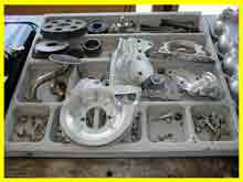
Engine components setup tray
Engine components
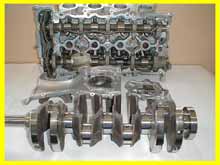
Measuring cylinder bore clearances
Measuring bearings to calculate vertical oil clearance
ENGINE ASSEMBLY HINTS
Setting up the engine…… This procedure when carried out correctly will eliminate a lot of interruptions during the course of assembly and also may identify some fundamental problems. A clean, well lit area with ample bench space to methodically lay out all components including nuts bolts and washers is essential. During this process of set up it is important to verify the correct engine parts have been chosen. To do this correctly the assembler has to have a good description of the engine he is assembling. Some times an engine could have been bored using the incorrect model pistons. All parts should be rechecked for their correct application. The assembler has to have the appropriate books available to check part numbers are suitably selected. A good assembler never assumes that the person before him has done his job correctly but re-inspects and checks all aspects of the reconditioning process. The person boring the engine could have been given pistons of incorrect compression ratio and even though this engine will run it may lack power or worse still ping its head off. Never assume anything, always check and become fully familiar with the engines you are assembling. Due to the fact that certain engines can be used in different models and for different applications several configurations of pistons, heads, tappet covers and sumps may be available. You would hope this has been sorted out before this stage but Murphy’s law necessitates the assembler to verify. You are the last line of defense and have a responsibility to ensure quality control is maintained.
Setting up should involve the placement and counting of every nut, bolt and washer in an order. All parts should be accounted for before any assembly is attempted. The last thing you want to be doing during assembly is wandering around looking for bits and pieces. This will only lead to frustration and the possibility of mistakes will increase.
The details of the engine you are about to assemble must be recorded in an assemblers record book. Model and engine number will normally be sufficient to identify the engine at a later date. Other important vital details will be recorded against the engine during assembly. Notes should also be recorded about any abnormal or unusual problems encountered during assembly.
Measurement and clearance checks…… The accuracy of the machining and grinding will have a big influence on the life of the reconditioned engine. Assemblers are required to ensure the components used are machined within these tolerances. Assemblers must have inside, outside and bearing micrometers to carry out this vital task. The piston to bore clearance, and big end and main vertical oil clearance should be calculated and recorded in the assemblers record book. This information will help determine the cause of a failure if it were to occur at a later date.
There are several acceptable methods to establish the clearance specifications.
Measuring the piston to bore clearance…… All the cylinder bores have to be measured for size, taper and ovality. Once you have established a bore size measure all the pistons. Measure the pistons at the correct position. Establish no damage has occurred during fitting to the rods. If a piston and rod assembly is dropped or even handled roughly the weight of the rod can enlarge the skirt at the contact point or even crack the skirt. The con rod cap has to be tensioned to specifications to the rod. When holding the rod in a vice be careful not to damage the rod or induce bend. The conrod tunnel is measured for out of round and bellmouthing. Record the inside micrometer reading as part of the calculation. Any rods found to be outside specifications should be rectified. At this point loosen the conrod nuts. All the bearing shells should be measured in the centre for thickness. Care has to be taken to ensure no bearing damage occurs. This measurement ensures all bearings were packaged correctly. This measurement should be within one or two tenths of a thousandth of an inch between each bearing shell. Record the highest reading which should be used in the vertical oil clearance calculation.Measure all the big end journals, checking for out of round and taper. Record the highest measurement and use this in your calculation. If the measurements were not within a couple of tenths of a thousands of an inch also carry out the calculation using the lowest measurement. The calculation is as simple as adding the measurement of two bearing shells to the measurement of the journal and subtracting the total from the tunnel measurement.This will give you the calculated or actual vertical oil clearance this particular engine has. If the calculation is within the book specifications record the answer in the assemblers record book. The basic procedure is the same for the mains.
: Every care has been taken in writing this information and procedures, but no responsibility can be excepted for errors, omissions or misuse of this information and procedures. The information available on this site is for your instruction only and cannot be copied for sale, © copyright 2020 UMR Engines www.engineproblem.com.au