QUESTION : (1) When the general term of "surface grinding " is used what is it describing?
Surface grinding is a process carried out on flat surfaces like block faces and cylinder head faces. The process is usually carried out with a segmented stone head of various grit grades depending upon the finish required. It is mostly used on cast iron components and the work piece is held in place while the stones rotate as the wheel moves over the face of the head or block in a controlled manner. These days it is more common to use a milling tip to machine flat surfaces, especially on aluminium components.
QUESTION : (2) How is a cylinder head evaluated for the need to surface grind?
A straight edge is used to check for straightness and a visual check for the finish, scratches or gasket bite. It is a general rule to skim almost all head gasket faces on alloy heads when replacing head gaskets. A minimum amount of material should be removed and the suitability of cylinder head thickness should be checked prior to machining. See CYLINDER HEAD THICKNESS CHARTS
QUESTION : (3) If an OHC cylinder head is bent what additional check has to be carried out before machining the face?
Verification that the cam turns freely will be necessary. The easiest and best method is to bolt the cam and caps into position and ensure they turn freely.
QUESTION : (4) If the OH cam does not turn freely what procedure is required before machining the face?
The position of the cam has to be restored to straight. Some designs with bolt on cam tunnels or pedestals can be machined straight on the top face of the head. Other heads without bolt-on pedestal tunnels will require straightening and in some cases may require tunnel boring as well. See "Engine Problem / Head - Bent."
QUESTION : (5) What is CBN tooling and what are the advantages?
CBN is short for CarbonBoronNitrate. This is an extremely hard man-made material that is used to make long life milling tips. They are in the form of a small disc that can be rotated in the tool holder to present a new cutting edge whenever required. They are normally double sided so they can also be turned over when all edge points are dull on the first side. The cost of these tips is high upwards of $400, but they produce a good finish over a long time period and are more economical and versatile than conventional tool steel or carbide tips. Being extremely hard they can successfully mill hardened materials such as pre-chambers or exposed inserts.
QUESTION : (6) Apart from cylinder head-gasket face, name other surfaces that may have to be machined or ground flat during engine recondition?
(a) Manifold position on the head (b) Thermostat mounting face on the head (c) Block face (d) Oil pump plate (e) Oil pump pick up flange.(bolted plate type) (f) Manifold face on the manifold. (g) Flywheel clutch face
90% to 100% correct answers indicate a good understanding of engine problems and functions. This web site is full of information that may improve your knowledge and skill.
QUESTION : (1) What is the basic difference between straightening a head and surface grinding a head?
Surface grinding removes material from the face and only straightens or restores the gasket face area to flat.Straightening a head refers to the process of physically straightening the head without grinding or milling. This process not only brings the face back to within grinding limits but also straightens the cam tunnel and the top face of the head. After straightening, the surface is skimmed to restore the gasket sealing area. When surface grinding a bent head without straightening, the head could end up with unequal amounts machined off the ends compared to the centre. This can effect compression's and as the head is still bent, the cam tunnel if OHC will still be bent causing possible cam seizure.
QUESTION : (2) Describe some methods of head straightening alloy heads?
The oldest method of straightening alloy heads requires the cylinder head to be controlled heated to around 260c to 300c., while having the bend removed by press or clamping plate. This method requires a considerable amount of over straightening to allow for spring back when the pressure and temperature are back to normal. This method is not very successful and can damage some heads beyond repair. Often a cylinder head will break in half rendering it useless. As this method requires the head to be heated above what is recommended by the manufacturer some softening of the head can occur. An alternate method was developed that does not require so much over bending of the cylinder head and only requires the head to be heated enough to take the chill out of the casting. This methods requires the head to be bent just a few thousand's of an inch over straight and to be held in that position while selected positions of the upper tappet cover area of the head are spot heated. The localised melting of these small areas act as locks to hold the head straight. The main advantage is the low heat applied to the head does not cause any change to the hardness of the head. This method requires less over bend as the selected areas heated cool down to form physical locks to hold the head straight.
QUESTION : (3) Some alloy heads can be straightened by surfacing both faces , top and bottom. Why can these heads be straightened this way?
Some OHC heads have bolt on camshaft pedestals which when removed allow the top face to be milled straight. After market pedestal shims are often available to allow restoration of camshaft height and rocker geometry...... Even this style of head should be straightened if the bend is bad, as this will reduce the amount of stock removal off both faces.
90% to 100% correct answers indicate a good understanding of engine problems and functions. This web site is full of information that may improve your knowledge and skill.
QUESTION : (1) What two general types of boring bars are commonly used by engine reconditioners?
Portable bar and a Vertical boring bar machine.
QUESTION : (2) Is it desirable to bore straight to the required o/s in one operation? If yes, give an explanation, if no, give an explanation.
No, it is better to bore in stages as the finish will be better and the distortion from heat less. From a large cut the tool can actually grow larger and blunter as it progressively goes down the bore.
QUESTION : (3) What is the recommended depth of the final cut when boring a cylinder?
The recommended depth of the final cut is .125 mm. (.005")
QUESTION : (4) Does a boring bar tool with a larger nose radius or with a smaller nose radius achieve a smoother finish?
The larger nose radius gives the smoother finish.
QUESTION : (5) What size should this tool nose radius be to achieve the smoother finish?
The best results have been achieved using a nose radius of around .5 mm. (.020")
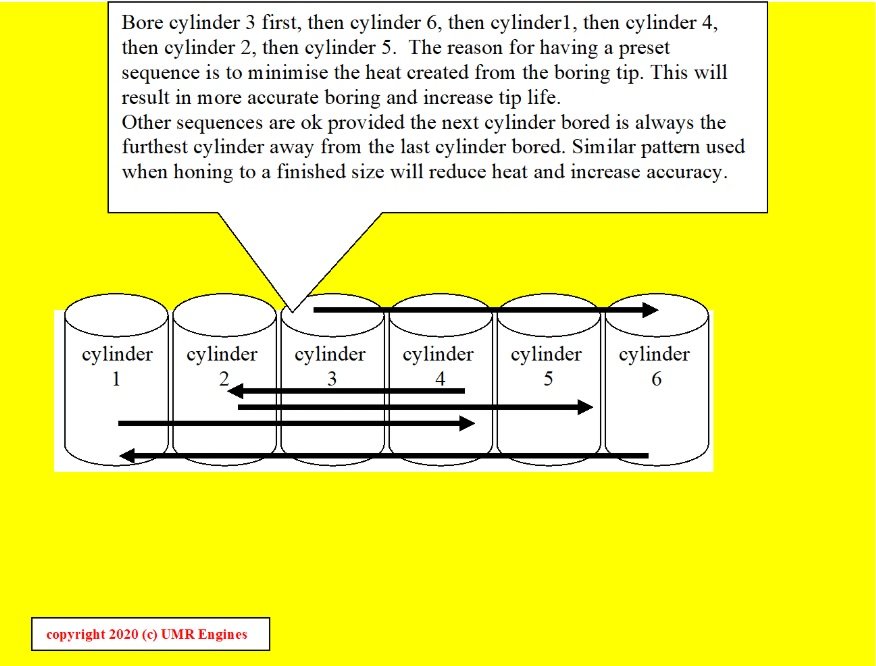
QUESTION : (6) Draw a plan diagram of a 6 cylinder block, number the cylinders 1 to 6. If boring number 3 cylinder first, work out the boring sequence that will achieve the best boring conditions. (Less heat and distortion)
90% to 100% correct answers indicate a good understanding of engine problems and functions. This web site is full of information that may improve your knowledge and skill.
QUESTION : (1) What is the purpose of honing a used bore that is being re-rung?
The hone is often referred to as a glaze break. As the bore size is already established the honing can be simply to break through bore glazing or bore polishing.
QUESTION : (2) What is bore glazing?
Bore glazing is a condition the bores develop if an engine suffers from excessive blow by during the run- in period. The condition is always recognisable by the distinct golden colour with the original hone pattern hi-lighted and unworn. This glazing or golden look is a chemical coating formed by the combustion passing by the rings, burning fragments of the cylinder bore and oil. This coating prevents complete run-in of rings and results in further fuming and glazing. Engines with glazed bores suffer from excess oil usage. Once an engine is glazed it usually requires a re-hone and the run-in procedure to re-commence.
QUESTION : (3) What is bore polishing?
Bore polishing is different from glazing in that it is not a chemical coating but the smoothing down of a bore area. Polishing is caused by carbon on a piston (usually above the top ring) being constantly rubbed up and down the bore physically polishing an area. Again blow-by will occur and possible ring scuffing. The engine has usually done a considerable amount of miles at this point and bore polishing is noticed at strip down. This has to be removed by re-honing before new rings can be fitted.
QUESTION : (4) Why can't we run the new rings on the re-machined bore without honing?
Boring bars leave boring bar marks which when magnified are seen as deep torn out grooves running parallel to the face. This surface is very unsuitable for running rings on and would destroy the rings within a few minutes. The honed finish removes these marks and establishes an ideal surface for rings to run on.
QUESTION : (5) How do we know if our hone pattern is ok?
The usual things to notice about hone patterns to determine if they are acceptable is firstly the cross hatch angle. Secondly the plateau area and thirdly the direction. The angle between the cross hatch should measure a minimum of 30 °. The plateau area should be around 50 % to 85% after rings have bed in. As the plateau area is the flat areas between the hone scratches or grooves a finer hone finish will generally result in a higher % of plateau after bed in has occurred. Honing with lighter pressure and finer stones will generally increase this plateau area. Ensure that there is no unidirectional honing. This is seen as heavy hone marks in one direction with little or no crosshatch. This condition will result in localised bore wear at the top and bottom of the bore. Ring land wear and ring wear are also accelerated.
QUESTION : (6) What amount of material should be left for honing after boring?
It is recommended that a minimum of .0025 " (.06mm) be left for honing. The first .002(0.05mm) being for boring bar mark removal and the remainder for establishing a correct hone finish for the rings.
QUESTION : (7) What grit stones should I use?
This is a complex question and will require some research as methods, ring types, engine types all determine what hone grit should be used. For most standard four cylinder petrol engine a hone stone of around 180 to 240 grit is recommended for stock removal, finishing off with a fine stone of closer to 400 for the final finish.
90% to 100% correct answers indicate a good understanding of engine problems and functions. This web site is full of information that may improve your knowledge and skill.
QUESTION : (1) Dry sleeves or plain repair sleeves are produced in several wall thicknesses. The three most commonly used being an "A" "B" and a "C" sleeve. What wall thickness are they?
The "A" section has a wall thickness of around .062" (1.6mm), a "B" section has around .093" (2.4mm) and a "C" of around .125" (3.2mm) (these are normal standard finished sizes)
QUESTION : (2) What section sleeve would be (most commonly)used to repair a block where the conrod had broken through the cylinder wall? And why?
A "B" section or thicker wall section sleeve would be desirable. An "A" section is ok when the repaired cylinder is still intact and has not broken through to the water jacket. Extra strength is required to support the sleeve if the parent bore is damaged or missing.
QUESTION : (3) What is the generally accepted crush applied to a sleeve when fitted in a cast iron block?
An interference fit of between .002" to .004" (.05mm to .10mm) (always check with manufactures if unsure.)
QUESTION : (4) When fitting a dry sleeve apart from the interference what should also ensure the sleeve cannot move in service?
When boring a block to accommodate a sleeve it is advisable to leave a small step at the bottom of the bore to prevent the sleeve moving down during engine operations.
QUESTION : (5) What has to be checked in the adjacent cylinders when sleeving a cylinder?
Due to the interference fit of the plain sleeve the adjacent bores should be checked for distortion. This distortion can normally be corrected with a ridged hone.
QUESTION : (6) If a block is bored to maximum o/s what check is important when selecting a sleeve?
It is advised to have at least .030" (.75mm) sleeve wall thickness when finished. If the selected sleeve has less advance to the next wall thickness. Eg. if an "A" section ends up less than .030" (75mm) go to a "B" which is around .030 (.75mm) thicker in wall section.
90% to 100% correct answers indicate a good understanding of engine problems and functions. This web site is full of information that may improve your knowledge and skill.
QUESTION : (1) How does a cam grinder know what shape to grind a cam lobe when they are all different from engine to engine?
Cam grinding machines unlike most cylindrical grinders always use a master that automaticly controlls the grinding wheel to duplicate the profile of the master. These masters are produced from blanks and are ground to the profile of a new or unworn cam lobe. The cam grinder keeps a series of masters in a library that allow selected profile grinding of worn camshafts. These masters can be factory purchased as computer ground finished masters or simply ground on the cam grinding machine using a new or good cam lobe and duplicating the profile onto the blank. These new masters are then cataloged for future grinding requirements.
QUESTION : (2) What is the most common finish fault when re-grinding camshafts?
Grinding chatter marks are often seen on the base circle and the sides of the lobe. Chatter marks can cause hydraulic lifter problems and premature wear. Pronounced chatter marks and eccentricity on the base circle can cause hydraulic lifter pump up and an engine miss on idle.
QUESTION : (3) What causes these chatter marks?
Due to the design of a cam grinder having a reciprocating grinding head that follows the master profile, any out of balance of the grinding wheel will cause a chattered finish. The camshaft has to be held rigid with a steady. This steady has to be adjusted correctly and positioned as close as possible to the lobe being ground. The chatter marks occur when the camshaft or grinding wheel are allowed to vibrate during the grinding process.
QUESTION : (4) Some cam designs require the lobe to be ground at an angle to assist in rotation of the lifter or follower. What two methods are used to achieve the desired angle when grinding?
The face of the grinding wheel can be dressed at the required angle or the grinding head work table can be adjusted to the required angle.
QUESTION : (5) Apart from finish, accuracy and concentricity what other items have to be considered when grinding a camshaft?
(a) The straightness of the cam before grinding. (.03mm. maximum allowable bend) (b) The indexing of the camshaft to ensure the correct cam timing is maintained. (c) The cam design can accommodate the passing of the conrods between the lobes and this clearance must be maintained when using new billets or cams of a different model from core stock. (Ford Falcons and Holdens are examples) Ensure correct undercut between lobes. (d) What effect the stock removal on a lobe will have on the rocker gear geometry or non- adjustable hydraulic tappets has to be considered. (e) The hardness of the cam lobe after regrinding.
90% to 100% correct answers indicate a good understanding of engine problems and functions. This web site is full of information that may improve your knowledge and skill.
QUESTION : (1) What type of machine is a crankshaft grinder?
A crankshaft grinder is a cylindrical grinder that has adjustable chucks to allow for grinding of big end journals. These chucks at each work head allow the crankshaft to be indexed and set up on the original crank journal axis. Due to the out of balance vibration created by the crank being offset in the chucks the wheel heads are provided with adjustable balance weights.
QUESTION : (2) Name two important procedures that reduce chatter and improve surface finish when grinding?
The grinding wheel has to be balanced with the adjustable weights provided. The work steadies adjusted correctly. The face of the grinding wheel has to be correctly dressed.
QUESTION : (3) What parts of the crankshaft are usually used to set up the crank ready for grinding the mains?
The unworn positions on the front main journal and the rear seal area are the most commonly used positions. Care has to be taken to ensure the chosen positions are true to the centre line and have not previously been reground incorrectly.
QUESTION : (4) What has to be checked and possibly redressed on the grinding wheel every time a different model crank is reground?
The radius on the wheel has to be matched to that on the crankshaft and checked against the manafacturers specifications. After regrinding the radii they should have the appearance of being smoothly blended into the existing radii. Incorrectly ground radii can cause fatigue cracks resulting in broken shafts
QUESTION : (5) What is meant by stroking a crankshaft during the regrinding operation?
The stroke of a crankshaft can be purposely altered to a predetermined specifications for the sake of a performance increase. This is achieved by offset grinding the con rod journals to an available under size or to a different replacement rod size.
QUESTION : (6) What other items have to be considered and addressed when "stroking" a crankshaft?
Due to the increase in stroke, compression, piston protrusion and physical engine clearances will have to be checked.(such as conrod to block clearance.) Due to the reduced strength of the crankshaft, shot peening, radii fillet rolling and balancing should all be considered.
QUESTION : (7) When grinding a crank is it the general practice to grind the mains first or the big ends first and why?
The big ends are generally ground first. (preferably from the centre out.) This allows for any movement that may occur as a result of grinding the big end journals to be present before grinding the mains. Any induced misalignment of the shaft will be corrected when lastly grinding the mains.
QUESTION : (8) What is nitriding?
Nitriding is a hardening process that is sometimes used to strengthen a crankshaft and make the journal surface more wear resistant.
QUESTION : (9) What depth does nitriding general penetrate the shaft to?
This will vary depending upon the application. As the depth is much less than induction hardened shafts the nitriding should be re- treated after every regrind.
QUESTION : (10) Why is it so important that the oil holes have an even and correct chamfer re-machined after regrinding?
The oil galleries are generally drilled at an angle through the shaft. Once the shaft is reground the edge of this oil drilling becomes very sharp and without re-work will quickly destroy the new bearing. Due to the angle of this cross drilling the edge is very thin and will start a crack out of the oil drilling if left without the correct chamfer.
90% to 100% correct answers indicate a good understanding of engine problems and functions. This web site is full of information that may improve your knowledge and skill.
Line boring is carried out where-ever a series of bearing positions have to be maintained in a straight line and to precise sizes. The series of bearing tunnels are usually closed down on the inside diameter and re-machined in a single process using a rigid boring bar to maintain the alignment. The machine is generally set up using the front and rear tunnel and not moved until all bearing tunnels are machined as a series.
QUESTION : (2) What other areas of an engine apart from main tunnels can require line boring?
The cam tunnels in a block or OHC tunnels in a cylinder head.
QUESTION : (3) As camshaft tunnels in a block are integral and cannot be closed like most main caps what is important to identify before boring the cam tunnels oversize?
It is important to know if oversize backed cam bearings are available before commencing the job.
90% to 100% correct answers indicate a good understanding of engine problems and functions. This web site is full of information that may improve your knowledge and skill.
QUESTION : (1) What type of welder is commonly used to weld alloy heads and blocks?
TIG welder.
QUESTION : (2) What does TIG stand for?
TIG stands for Tungsten, Inert Gas. The correct name being GTAW or Gas, Tungsten, Arc Welding.
QUESTION : (3) What is the principal of TIG welding?
A TIG uses an inert gas as the flux to protect the weld from oxidation. Electric arc is used to heat the metal being welded by passing the current through a non consumed tungsten rod. The arc heats the metal to a molten pool where filler rod is added by hand. (GTAW)
QUESTION : (4) There are several gases used as a shield. What is the gas most commonly used by engine reconditioners to weld alloy heads?
Argon
QUESTION : (5) What is the most important part of the welding process when welding corroded alloy heads?
Grinding out all of the corrosion damage leaving no trace of oxides or impurities. The smallest amount of corrosion left at the weld site will cause the weld to be inferior and full of porosity. It is better to have a larger clean area to weld than a smaller dirty area. Use tungsten alloy burrs to remove corroded alloy as abrasive burrs leave contaminates behind spoiling the weld.
QUESTION : (6) What are some of the advantages of welding alloy heads with TIG?
TIG allows good heat control resulting in less distortion. TIG also does not splatter allowing welding to be performed close to machined surfaces without splatter damage. TIG gives easy change of filler rod size as filler rod is added by hand.
90% to 100% correct answers indicate a good understanding of engine problems and functions. This web site is full of information that may improve your knowledge and skill.